


Industrial Pulp Molding Process for Molded Fiber Packaging
Learn how recycled fiber is transformed into custom industrial molded fiber packaging through pulp preparation, vacuum forming, dewatering, wet-product transfer, drying and optional finishing. Each process stage must be matched to the finished product, mold structure and production requirements.
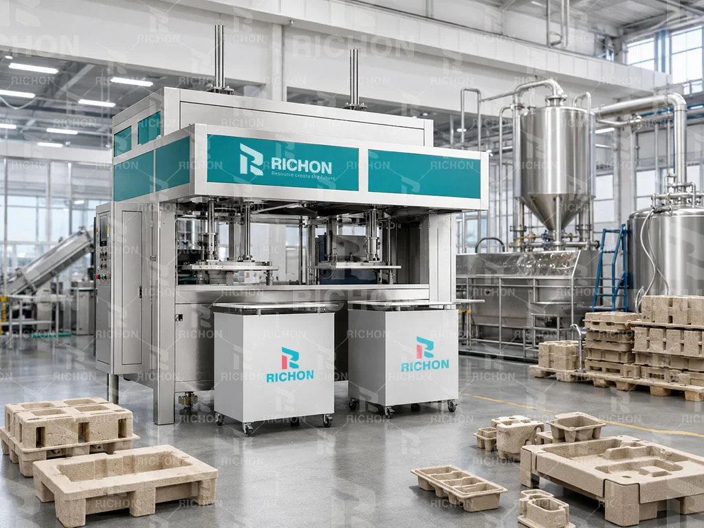
What Is the Industrial Pulp Molding Process?
Industrial pulp molding is a wet fiber forming process used to convert prepared pulp into three-dimensional molded fiber packaging. The process combines pulp preparation, vacuum forming, water removal, wet-product handling, drying and optional finishing.
The industrial pulp molding process begins with fibers dispersed in water to form a pulp suspension. Vacuum draws the fibers onto a product-specific mold while water passes through the mold surface and drainage structure.
The resulting wet molded fiber part is then dewatered, released or transferred from the forming mold, dried, and—when the finished packaging requires it—subjected to optional shaping, hot pressing or trimming.
Because industrial packaging products vary in dimensions, molded weight, cavity depth and geometry, forming, dewatering and drying conditions are product-specific rather than fixed for every package.
How Wet Pulp Becomes a Three-Dimensional Package
Each stage prepares the molded fiber structure for the next process, so production stability depends on the complete sequence rather than one machine operation alone.
Wet Pulp Molding
Fibers are dispersed in water and deposited onto a mold through vacuum-assisted forming. Water is removed during forming and dewatering, followed by drying.
This is the process route covered throughout this Richon engineering guide.
Dry Molded Fiber
Dry molded fiber technologies use a different fiber preparation and forming route and should not be treated as the same production process as conventional wet pulp molding.
Equipment, tooling, forming conditions and downstream processing can therefore differ significantly between the two technologies.
Why Process Settings Cannot Be Identical for Every Product
An industrial protective insert and a shallow molded fiber tray can require different forming and drying conditions. Richon therefore evaluates the finished product, mold and production target together when determining the process configuration.
Raw Materials and Fiber Preparation for Industrial Pulp Molding
Before vacuum forming begins, the raw fiber must be converted into a stable and sufficiently uniform pulp suspension. Material selection, contaminant removal, pulping and screening influence how consistently fibers can later deposit onto the mold.
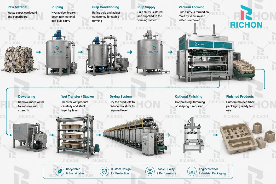
The objective is not simply to turn paper into water. Fiber preparation must create a stable, pumpable and formable pulp suspension for the downstream molding process.
Industrial pulp molding commonly starts with suitable recycled paper or paperboard-based fiber materials. These materials are sorted, reduced to a manageable size when required, dispersed in water through pulping, screened, and then stored or circulated as prepared pulp before entering the forming process.
Raw Material Selection
Suitable recycled paper and paperboard-based fiber materials are selected according to the required molded product, process behavior and quality target.
Sorting & Preparation
Obvious contaminants or unsuitable materials should be removed before pulping. Large material can also be reduced in size where required for more stable feeding.
Hydrapulping
Fiber material is mixed with water and mechanically dispersed so that paper structures break down and individual fibers can form a pumpable pulp suspension.
Screening & Cleaning
Screening helps remove unwanted contaminants and oversized material that could interfere with pumps, piping, mold drainage or stable fiber deposition.
Pulp Storage & Circulation
Prepared pulp is stored and circulated before forming. The next stage controls pulp condition and supply so that the molding section receives a sufficiently stable fiber suspension for repeatable production.
Does Every Paper Fiber Behave the Same?
No. Different fiber sources can vary in fiber length, cleanliness, previous recycling history and processing behavior . These differences can influence pulping, drainage, molded-product strength and surface appearance.
Raw Material Preparation Directly Affects the Forming Stage
Stable industrial pulp molding starts before the forming machine. Poorly prepared pulp can make downstream fiber deposition and dewatering more difficult to control, while consistent pulp preparation provides a more stable basis for vacuum forming.
Pulp Preparation and Conditioning Before Vacuum Forming
Before pulp enters the forming section, the fiber suspension must be maintained at a suitable and stable condition. For industrial molded fiber production, pulp feed consistency is adjusted according to the product, mold structure and forming requirements rather than using one fixed setting for every application.
For Richon industrial molded fiber forming applications, the pulp consistency supplied to the forming process is typically around 3%–5%. The actual setting can vary according to the molded product, product weight, geometry, fiber condition, mold drainage and required forming performance.
This value refers to the pulp condition supplied toward the forming process and should not automatically be treated as a universal pulping consistency for every upstream tank or pulping stage.
Why Is the Pulp Consistency Adjusted?
Different molded fiber products do not require exactly the same pulp condition. A lightweight packaging insert, a deeper protective end cap and a heavier structural tray may respond differently during vacuum deposition and drainage.
The operating consistency therefore needs to be matched with the actual product and mold rather than selected from a single fixed number.
Pulp Consistency
The forming pulp must contain enough suspended fiber to build the required molded structure while still allowing effective water drainage through the forming mold.
Fiber Distribution
Fibers should remain sufficiently dispersed throughout the pulp suspension so that the forming mold receives a more uniform fiber supply during each forming cycle.
Mixing and Circulation
Mixing and circulation help reduce fiber settling and maintain a more stable pulp condition before the suspension reaches the forming section.
Pulp Cleanliness
Foreign material, oversized contaminants or unstable pulp conditions can interfere with mold drainage, fiber deposition and finished product consistency.
Product Requirements
Product dimensions, molded weight, wall geometry and required packaging performance influence the pulp condition selected for production.
Stable Pulp Supply
Stable delivery to the forming section helps reduce unnecessary variation between production cycles and supports more repeatable wet product formation.
Are Pulp Additives Always Required?
No. Additives are selected according to the required performance of the finished molded fiber packaging and the customer’s application. There is no single additive recipe that should be applied to every industrial pulp molding product.
When additional water resistance, wet strength or other functional properties are required, the pulp formulation can be adjusted as part of the overall product-specific process design.
Pulp consistency should follow the product and forming requirement. A higher or lower consistency is not automatically better. The goal is to establish a stable pulp condition that works together with the product geometry, mold drainage and forming cycle.
How Vacuum Forming Creates the Molded Fiber Structure
Vacuum forming is the stage where the prepared pulp suspension begins to take the three-dimensional shape of the finished molded fiber packaging. A pressure difference draws water through the forming mold, while fibers are retained on the mold surface and gradually build the wet molded structure.
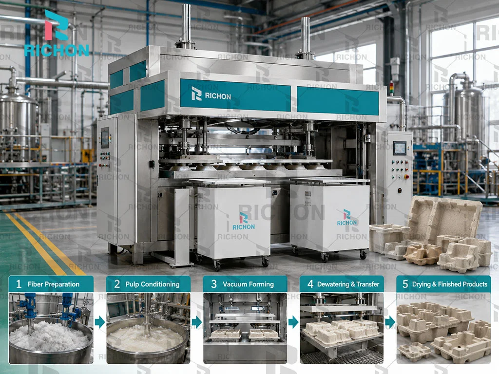
During vacuum forming, water passes through the permeable forming mold while suspended fibers remain on the mold surface and build the wet molded fiber product.
In Richon industrial molded fiber applications, the forming vacuum is typically around -0.05 to -0.07 MPa. The actual operating setting is adjusted according to the product geometry, pulp condition, mold drainage characteristics and required forming performance.
The forming time is also product-specific. A single fixed forming time should not be applied to every industrial molded fiber product, because product depth, molded weight, cavity structure and drainage behavior can all change the required cycle.
Why Is the Vacuum Level Not Fixed for Every Product?
The vacuum must work together with the pulp condition and the drainage structure of the forming mold. A shallow protective insert and a deep industrial end cap may not require exactly the same operating conditions.
The practical setting should therefore be selected according to actual forming performance rather than treating the highest possible vacuum as automatically better.
What Actually Happens During Vacuum Pulp Forming?
Pulp Suspension Reaches the Forming Mold
Conditioned pulp containing suspended fibers and water is supplied to the forming section so that the product-specific mold can contact the pulp suspension.
Vacuum Creates a Pressure Difference
The vacuum system creates a pressure difference across the permeable mold surface. This pressure difference drives water toward the mold drainage structure.
Water Passes Through the Mold
Water moves through the forming surface, mesh and internal drainage passages of the mold and is carried away through the vacuum and water handling system.
Fibers Remain on the Forming Surface
Fibers are retained instead of passing through the mold. As the process continues, they accumulate across the mold surface and begin reproducing the required packaging geometry.
The Wet Fiber Layer Builds Up
Fiber deposition continues until the developing wet part reaches the required molded structure and weight range for the selected product and production process.
Forming Transitions to Dewatering
After sufficient fiber deposition, continued drainage helps reduce the water carried by the wet product and prepares it for release, transfer and subsequent drying.
Which Vacuum Pump Can Be Used for Industrial Pulp Molding?
Richon can configure different vacuum pump technologies according to the customer’s budget, production requirements and overall project configuration. There is no single vacuum pump type that must be used for every industrial molded fiber production line.
Roots Vacuum Pump
A Roots-type vacuum system can be considered when the production project requires a vacuum configuration suited to the selected forming process and overall system design.
Water-Ring Vacuum Pump
Water-ring vacuum pumps are another common option for wet pulp molding systems and can be configured according to the required vacuum performance and project conditions.
Oil-Free Screw Vacuum Pump
Oil-free screw vacuum technology can also be selected where its operating characteristics, maintenance approach and project budget match the customer’s requirements.
Pump type, system capacity and supporting equipment should be matched with the forming machine, product characteristics, required vacuum performance, operating conditions and investment plan.
Mold Drainage Is Part of the Forming Process
Vacuum performance alone does not determine whether the product forms correctly. The geometry, forming surface and drainage structure of the mold also control how water leaves the pulp suspension and how fibers accumulate across the product.
Deep areas, corners, ribs and large changes in product geometry can influence local fiber deposition and drainage. This is why the pulp molding mold design must be developed together with the forming process rather than treated as an independent component.
Product Geometry
Mold Drainage
Pulp Condition
Vacuum Stability
Molded Weight
Forming Time
Is the Forming Time the Same for Every Molded Fiber Product?
No. Forming time is adjusted according to the product being produced. A heavier or deeper molded fiber component can require a different forming condition from a lighter or shallower protective insert.
Product dimensions, molded weight, cavity layout, fiber deposition, mold drainage and wet-product stability should therefore be evaluated together when establishing the production cycle.
More vacuum is not automatically better. Stable molded fiber forming depends on the balance between pulp condition, vacuum level, mold drainage, product geometry and forming time. The objective is repeatable fiber deposition and reliable wet-product formation.
Dewatering and Wet Product Transfer Before Drying
After the required fiber layer has formed on the mold, the wet molded fiber product still contains a large amount of water. Continued dewatering reduces this water load and gives the wet part enough stability to be released from the forming mold and moved toward the drying stage.
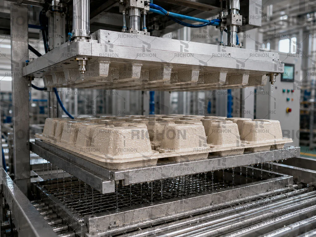
After vacuum forming, additional water is removed from the wet molded fiber product before reverse air blowing releases the product from the forming mold.
Before drying, the moisture content of an industrial molded fiber wet product is typically around 60%–75%. The actual value varies according to the product, molded weight, geometry, forming condition, mold drainage and dewatering time.
After sufficient dewatering, Richon industrial pulp molding systems can use reverse air blowing through the forming mold to release the wet product from the mold surface before it moves to drying or the next handling stage.
Why Does Wet-Product Moisture Matter?
The amount of water remaining in the molded product directly affects both wet-part handling and the load placed on the drying system. Excess water means that more moisture must later be evaporated.
However, the objective is not simply to remove as much water as possible during forming. Dewatering must be balanced with production cycle time, product stability and reliable release from the mold.
What Happens After the Wet Fiber Layer Is Formed?
Wet Product Forms on the Mold
Vacuum forming builds the required fiber layer on the product-specific forming mold. At this stage, the molded part has taken shape but still carries substantial water.
Continued Dewatering
Water continues to pass through the permeable forming surface and drainage structure, reducing the moisture carried by the wet molded fiber part.
Wet-Part Stability Develops
As water is removed, the wet product becomes sufficiently stable to retain its molded geometry during release and subsequent handling.
Reverse Air Blowing Releases the Product
Once the required dewatering condition is reached, reverse air blowing through the forming mold helps separate the wet molded fiber product from the mold surface.
Wet Product Leaves the Forming Position
After demolding, the wet product is moved away from the forming position using the handling arrangement designed for the selected machine and production process.
Product Moves Toward Drying
The released wet product is then prepared for air drying, metal drying or another drying configuration selected for the actual production project.
How Does Reverse Air Blowing Release the Wet Product?
During forming, vacuum helps hold the developing fiber layer against the mold surface. When forming and dewatering are complete, the process transitions from holding the wet product on the mold to releasing it.
Reverse air blowing applies air through the forming mold in the opposite direction to help separate the wet molded fiber part from the forming surface. The product can then move into the next handling or drying stage.
Fibers are retained on the mold surface.
Additional water is removed from the wet product.
Air assists separation from the forming mold.
The product is ready for downstream handling.
What Affects Dewatering and Wet-Part Release?
Molded Product Weight
Heavier molded fiber products generally carry more fiber and water, which changes the required dewatering and handling condition.
Product Geometry
Deep cavities, ribs, corners and structural features can influence drainage and how easily the wet product releases from the mold.
Mold Drainage
The forming surface and internal drainage passages influence how efficiently water can leave different areas of the wet product.
Dewatering Time
The required time is product-specific and must be balanced with wet product stability and the overall production cycle.
Moisture Condition
The remaining moisture affects wet strength, handling reliability and the amount of water that must later be removed during drying.
Release Timing
Reverse air release must occur when the wet molded product has sufficient stability to leave the forming mold without unnecessary deformation.
More Dewatering Is Not Automatically Better
Removing additional water before drying can reduce the moisture load carried into the dryer, but excessive dewatering time can also extend the forming cycle and reduce production efficiency.
The correct process should balance wet-part stability, release reliability, cycle time and downstream drying load for the actual molded fiber product.
Dewatering is the bridge between vacuum forming and drying. The goal is not simply to achieve the lowest possible moisture level, but to create a wet product that can release reliably, retain its geometry and enter the drying stage with a manageable moisture load.
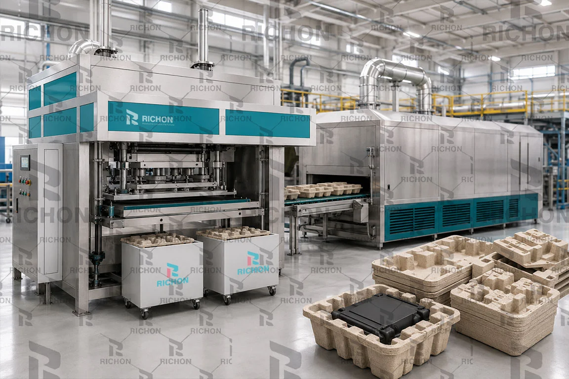
When Are Hot Pressing, Shaping and Trimming Needed?
Drying does not always represent the final production step. Depending on the finished packaging requirements, industrial molded fiber products can undergo optional hot pressing, dimensional shaping, calibration or trimming before final inspection and delivery.
Hot pressing, shaping and trimming are product-specific finishing processes. They are used when the molded fiber packaging requires improved surface definition, dimensional stability, controlled edges or closer fit with the customer’s packaged product.
For common Richon industrial molded fiber applications, hot shaping can typically use a 180–220°C mold temperature, a 40-ton shaping press and a 5–7 second pressing cycle. The actual setting is adjusted according to product geometry, material condition and finished-product requirements.
The mold temperature is selected to support surface refinement and dimensional shaping of the dried or conditioned molded fiber product.
A 40-ton shaping press is a common Richon configuration for industrial molded fiber finishing. The required machine tonnage still depends on the actual mold size and product.
The dwell time is adjusted according to product geometry, material condition and required shaping result rather than treated as one fixed cycle for every molded fiber product.
Does Every Molded Fiber Product Need Hot Pressing?
Suitable when the product already meets fit, structural, dimensional and surface requirements.
Use hot pressing, shaping or trimming when additional control is required.
What Does Each Finishing Process Do?
Hot Pressing
Hot pressing places the molded fiber product between heated shaping molds so that heat and mechanical force can refine the product surface and improve dimensional consistency.
- Improves surface definition
- Supports dimensional refinement
- Can improve product flatness
- Helps stabilize selected structural features
Shaping / Calibration
Shaping or calibration is used when specific dimensions, contact surfaces or product-fit areas need tighter control after the drying stage.
- Improves fit with the packaged product
- Controls selected dimensions
- Refines mating or support surfaces
- Reduces unwanted deformation
Trimming
Trimming can remove unwanted fiber edges or define openings and selected product boundaries where the packaging design requires more controlled edge geometry.
- Controls finished edges
- Creates cleaner openings
- Supports assembly requirements
- Improves final product appearance
How Should Hot Pressing Parameters Be Set?
Temperature, machine tonnage and dwell time must work together with the product geometry and material condition. Increasing only one parameter does not automatically produce a better finished product.
In common Richon applications, a 180–220°C shaping temperature and approximately 5–7 seconds of pressing time can be used as a practical starting range with a 40-ton shaping press. Final settings are confirmed through actual product trials.
Does Longer Hot Pressing Always Give a Better Result?
Within an appropriate process window, increasing dwell time can help improve shaping and dimensional stabilization because the product remains under controlled heat and pressure for longer.
However, longer pressing also increases cycle time. The final setting should therefore balance shaping quality, product geometry, material condition and production efficiency rather than simply maximizing pressing time.
What Determines Whether Additional Finishing Is Needed?
Surface Requirement
Products that require a smoother or more controlled surface may benefit from additional hot shaping.
Dimensional Accuracy
Packaging with tighter fit requirements may need calibration or shaping after drying.
Edge Definition
Selected designs can require trimming when the final product needs cleaner or more controlled edges.
Product Geometry
Complex ribs, support surfaces and mating areas can influence the need for additional shaping.
Product Fit
Protective molded fiber packaging must match the customer’s actual product closely enough to support positioning and protection.
Customer Standard
The final process should follow the customer’s packaging quality, appearance and dimensional requirements.
More finishing does not automatically mean better packaging. Hot pressing, shaping and trimming should only be added when they help the molded fiber product meet the required surface, dimensional, fit or edge standard. The process should be designed around the finished packaging requirement, not around adding unnecessary steps.
What Determines Industrial Molded Fiber Product Quality?
Molded fiber product quality is created across the complete production process. Fiber preparation, pulp condition, vacuum forming, mold drainage, wet-product handling, drying and optional finishing all influence the final packaging result.
In Richon industrial molded fiber projects, final inspection can include edge forming quality, cracks on the A-side and B-side, molded product weight and other customer-specific requirements.
There is no single universal quality tolerance for every molded fiber product. Inspection criteria and process settings should be defined according to the customer’s approved packaging design, sample and application requirements.
What Does Richon Check on Molded Fiber Products?
The exact inspection plan depends on the project, but the following checks are commonly relevant when evaluating custom industrial molded fiber packaging.
Edge Forming Quality
Product edges are checked to determine whether the molded shape is properly formed and whether unwanted fiber accumulation, damaged edges or poorly defined areas affect the finished packaging.
A-Side & B-Side Condition
Both sides of the molded fiber product are visually inspected for cracks and other defects that may affect appearance, structure or packaging performance.
Molded Product Weight
Finished product weight is checked against the target specified for the approved product. Molded weight provides an important indication of whether the required amount of fiber has been formed into the product.
Customer-Specific Requirements
Additional inspection items can be defined according to the customer’s packaged product, application, dimensional requirements and agreed quality standard.
Why Is There No Single QC Standard for Every Industrial Paper Tray?
Industrial molded fiber packaging is usually developed around a specific customer product. A protective tray for an electronic product can have different geometry, molded weight, fit and surface requirements from packaging designed for an automotive component.
For this reason, Richon determines the production process and inspection criteria according to the confirmed product design and customer requirements rather than applying one fixed tolerance to every molded fiber product.
Finished Product Quality Starts Before Final Inspection
Final inspection can identify whether the product meets the required result, but most quality characteristics are created much earlier in the production process.
Which Process Factors Influence Molded Fiber Quality?
Fiber Preparation
Fiber condition and cleanliness influence pulp stability, drainage behavior and the consistency of the molded structure.
Pulp Consistency
The pulp feed condition affects how much fiber reaches the forming mold and how the fiber layer develops during vacuum forming.
Fiber Distribution
Uneven fiber deposition can create areas with different molded thickness, weight distribution or structural behavior.
Vacuum Stability
Stable vacuum helps maintain repeatable water drainage and fiber deposition during each forming cycle.
Mold Geometry & Drainage
Mold shape, drainage passages and forming-surface design influence how fibers build around corners, ribs, deep areas and product edges.
Wet-Product Release
The wet product must release from the forming mold without unnecessary deformation or damage before entering downstream drying.
Drying Uniformity
Uneven moisture removal can influence dimensional stability, deformation and the finished condition of the molded fiber product.
Optional Finishing
When required, hot pressing, shaping and trimming can help refine surface condition, dimensions, fit and edge quality.
From Approved Sample to Production Quality
For a customized molded fiber project, the approved sample provides an important reference for production. Once the customer confirms the sample, the manufacturing process can be adjusted to reproduce the required product condition during normal production.
Quality control therefore focuses on whether production pieces continue to meet the agreed characteristics rather than comparing every industrial packaging product with one generic specification.
Customer-confirmed sample and design establish the required finished result.
Forming, drying and finishing conditions are matched to the required product.
Edges, A/B surfaces, molded weight and project-specific criteria are checked.
Finished packaging meets the confirmed customer requirement.
What Should Be Reviewed When Product Quality Changes?
A visible defect does not always have one single cause. The relevant process areas should be reviewed together before changing machine settings.
| Observed Issue | Process Areas to Review |
|---|---|
| Poor edge definition | Fiber deposition, mold geometry, drainage, product release and optional shaping or trimming |
| Cracks on A-side or B-side | Fiber distribution, wet-product condition, release, drying and finishing process |
| Molded weight outside target | Pulp feed condition, forming cycle, fiber deposition and process repeatability |
| Product deformation | Wet-part stability, handling, drying uniformity and optional shaping conditions |
A stable finished product depends on the complete interaction between fiber preparation, pulp condition, vacuum forming, mold design, dewatering, release, drying and finishing. Quality problems should therefore be analyzed across the full production process rather than attributed automatically to one machine component.
Industrial Pulp Molding vs Egg Tray Production
Industrial protective packaging and egg trays can both use wet pulp molding, vacuum forming and drying, but their production priorities are different. Standard egg tray production focuses on repeated output of a defined tray format, while industrial packaging is more dependent on the customer’s product geometry and custom mold configuration.
Industrial pulp molding and egg tray production share the same basic wet-forming principle: fibers are suspended in water, deposited onto a mold by vacuum, dewatered and dried. The main difference is that industrial molded fiber packaging is usually engineered around a specific customer product, while egg tray production is built around standardized tray geometry and repeatable high-volume output .
Both Belong to Wet Pulp Molding
The fundamental production mechanism is similar. Fiber is prepared in water, formed on a permeable mold, dewatered and then dried. The difference appears mainly in product design, tooling, process settings and project priorities .
| Comparison | Industrial Molded Fiber Packaging | Standard Egg Tray Production |
|---|---|---|
| Primary Product | Custom protective trays, inserts, end caps and other product-specific molded fiber packaging. | Standardized egg trays produced around a defined tray format and repeatable packaging function. |
| Product Geometry | Can vary significantly between projects depending on the packaged product and required protection. | Geometry is comparatively standardized once the selected egg tray design is confirmed. |
| Mold Design | Mold dimensions, cavity layout and geometry are commonly customized around the customer’s packaging product. | Tooling is configured around a defined egg tray design and production format. |
| Production Capacity | Capacity is calculated from product geometry, cavity quantity, forming cycle, molded weight and operating efficiency. | Capacity can normally be communicated more directly in trays per hour because the product format is standardized. |
| Forming Priority | Focus on product-specific fiber distribution, mold drainage, transfer reliability and required geometry. | Focus on stable repetition, tray consistency and continuous production throughput. |
| Wet Transfer | Transfer conditions can vary according to cavity depth, molded weight and custom product geometry. | Transfer is designed around the selected standard egg tray configuration and production cycle. |
| Drying Basis | Dryer configuration should follow product weight, incoming moisture, geometry and product-specific output. | Drying can be matched around a more standardized tray weight, production capacity and selected line configuration. |
| Optional Finishing | Hot pressing, shaping or trimming may be added when dimensional, surface or edge requirements justify them. | Standard egg trays typically emphasize functional forming and drying rather than complex downstream finishing. |
| Quality Priority | Protection, fit, dimensional stability, geometry and application-specific performance. | Tray consistency, stacking, egg protection and stable high-volume production. |
| Starting Project Information | Product sample, drawing, dimensions, packaging function, molded weight target and production requirement. | Required egg tray type, tray capacity, target trays per hour, drying conditions and factory requirements. |
Product First vs Capacity First
Industrial packaging projects usually start with the finished packaging product, then determine mold and capacity. Egg tray projects can normally start from a required standardized trays-per-hour production target.
Custom Mold vs Standardized Format
Industrial packaging requires more product-specific tooling decisions, while egg tray tooling is based around a comparatively stable and repeatable tray format.
Process Flexibility vs Repetitive Output
Industrial packaging emphasizes flexibility for different geometries. Egg tray production places greater emphasis on repeatable production of the same tray at stable throughput.
Why Industrial Capacity Cannot Be Judged by One Fixed pcs/h Number
A large protective insert and a small positioning tray can use the same general pulp molding principle but have very different cavity layouts and forming cycles. Industrial capacity therefore follows the actual product and mold configuration .
The Manufacturing Principle Is Similar, but the Project Logic Is Different
Both processes can use fiber preparation, vacuum forming, dewatering and drying. The key difference is the engineering starting point. Egg tray production starts from a standardized tray and target output, while industrial molded fiber projects start from the customer’s packaging product and then determine tooling, forming conditions, capacity and drying requirements.
Industrial Pulp Molding Process FAQ
Industrial molded fiber packaging is a product-specific process. Machine configuration, mold design, forming conditions, drying and finishing should therefore be developed around the customer’s actual packaging product rather than selected from one fixed production formula.
From Customer Sample to Approved Molded Fiber Product
When Richon receives a customer’s existing packaging sample, the project begins with reverse engineering and dimensional mapping. The measured data is then used to design the molded fiber packaging mold so that the new molded product can reproduce the required packaging structure and fit.
The customer confirms the mold drawing before tooling proceeds. Samples are then produced for a second confirmation. Normal production and delivery begin only after the customer approves the final sample.
Customer Sample
The customer’s existing packaging sample provides the starting reference for product geometry, structure and fit requirements.
Reverse Engineering
The sample is measured and mapped so that the packaging geometry can be converted into usable mold-design data.
Packaging Mold Design
Mold structure is developed from the reverse-engineered product data to reproduce the required molded fiber packaging geometry.
Drawing Confirmation
The mold design drawing is sent to the customer for review and confirmation before the project moves into sample production.
Sample Production
Trial molded fiber products are produced so that the actual geometry, surface, fit and forming result can be evaluated.
Second Confirmation
The produced sample is submitted to the customer for a second review against the required packaging product.
Final Approval
After the customer approves the sample, the confirmed product becomes the reference for normal manufacturing and quality control.
Production & Delivery
Normal production begins according to the confirmed product, process requirements and agreed project specifications.
For custom industrial molded fiber packaging, Richon first defines the product and mold requirements. Production capacity, forming cycle, drying load and machine configuration are then evaluated around the confirmed molded product.
Industrial Pulp Molding Process Questions
These answers summarize the main engineering decisions involved in custom industrial molded fiber production.
01 What is the industrial pulp molding process?
The industrial pulp molding process is a wet fiber forming process used to manufacture three-dimensional protective molded fiber packaging.
Fiber is dispersed in water and conditioned into a suitable pulp suspension. For Richon industrial forming applications, the pulp feed consistency is typically around 3%–5%, although the actual setting varies according to the product.
Vacuum then removes water through a product-specific forming mold while fibers remain on the mold surface. The resulting wet product is dewatered, demolded, dried and, where required, finished through hot pressing, shaping or trimming.
02 What raw materials can be used for industrial molded fiber packaging?
Suitable recycled paper and paperboard-based fiber materials can be used for industrial molded fiber packaging. The selected material should be evaluated according to fiber condition, cleanliness, forming behavior and the performance required from the finished packaging.
Different fiber sources can behave differently during pulping, drainage and vacuum forming, so raw material selection should be considered together with the mold and production process.
03 How does vacuum forming work in pulp molding?
Vacuum creates a pressure difference across the permeable forming mold. Water passes through the mold surface and drainage structure, while fibers remain on the mold and gradually build the wet molded fiber product.
For Richon industrial molded fiber applications, the forming vacuum is typically around -0.05 to -0.07 MPa. The actual setting depends on product geometry, pulp condition, mold drainage and forming requirements.
Depending on the project budget and technical requirements, the vacuum system can use a Roots vacuum pump, water-ring vacuum pump or oil-free screw vacuum pump.
04 Why are dewatering and wet-product transfer important?
The molded fiber product still contains a large amount of water immediately after forming. Before drying, wet-product moisture is typically around 60%–75%, although the actual value varies according to the product and dewatering condition.
Dewatering helps the wet product develop enough stability for demolding. Richon systems can then use reverse air blowing through the forming mold to separate the wet product from the mold surface before downstream handling and drying.
05 How is industrial pulp molding production capacity calculated?
Industrial molded fiber production capacity is product-specific and should not be represented by one fixed pieces-per-hour figure for every customer project.
Capacity is evaluated from factors such as product dimensions, molded weight, mold cavity layout, forming cycle and practical operating conditions.
06 How is the drying system selected for industrial molded fiber products?
The drying system is selected according to production volume, product characteristics, project cost, factory conditions and the amount of moisture that must be removed from the wet product.
Air or natural drying can be used where investment needs to be controlled and sufficient drying conditions are available. For higher-volume production, a metal drying system can provide a more continuous and controlled drying process.
Dryer capacity should be evaluated from the actual moisture-removal load rather than pieces per hour alone.
07 Is hot pressing required for every molded fiber product?
No. Hot pressing is an optional finishing process and is only added when the product requires additional surface definition, dimensional stability, fit or shaping.
For common Richon industrial molded fiber applications, hot shaping can typically use a mold temperature of 180–220°C, a 40-ton shaping press and a pressing time of approximately 5–7 seconds.
The final process setting is adjusted according to product geometry, material condition and finished-product requirements.
08 What information is needed to evaluate an industrial pulp molding project?
The most useful starting point is information about the actual molded fiber packaging product. A physical sample is especially useful because it allows Richon to reverse-engineer the packaging geometry and begin mold design.
Where available, customers can also provide product dimensions, drawings, CAD or 3D data, target molded weight, required production volume and other packaging requirements.
After the sample or design data is evaluated, Richon develops the packaging mold drawing for customer confirmation, produces trial samples for a second confirmation and proceeds with normal production after final approval.
What Should You Send Richon First?
The more accurately the finished packaging product can be defined, the more accurately the mold, forming process and production system can be evaluated.
Existing tray, insert, end cap or protective molded fiber product.
Overall size and important product-fit dimensions.
Technical drawings or digital product data where available.
Required product weight where an existing specification is available.
Target daily, hourly or annual production requirement.
Available space and relevant local operating conditions for the project.
Turn Your Packaging Product Into a Pulp Molding Process Plan
Send Richon your existing sample, product dimensions or packaging drawing. Our engineering evaluation can start from the molded product, then define the mold, forming requirements, production capacity, drying method and equipment configuration around the actual project.